Welcome to our Web Site!

Before You Start

Home
Testing
Before You Start
Our Services
Packing List
Contact Us
NOS Stators
Husqvarna
KTM
Bultaco
Montesa
Mini 6 Pole
Accolades

Add your content here

There are a few easy steps we can take to make the Motoplat Repair go smoothly. Before removal of the motoplat mark one of the screw holes on the Motoplat and mounting bracket so you can align the Motoplat in the same position as it was removed. Next mark the Motoplat mounting bracket to the engine case so if removed it can also be aligned in the correct position.


Note the pictures below with highlighted areas. Now you should be able to assemble the mounting plate and Motoplat stator in the exact postion it was removed with the same timing when returned repaired.

p4300274.jpg

markingit.jpg

There are a couple of other things we must check before sending in for repair.

Step 1:

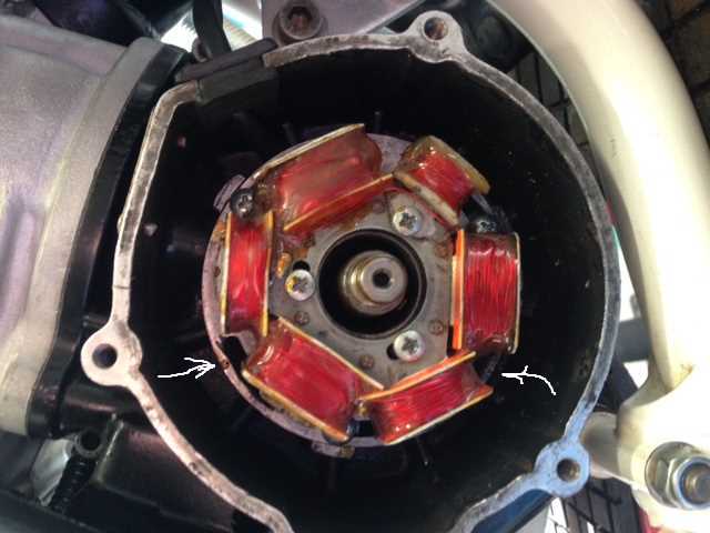
There are two basic types of Motoplat stators. This by the way is not the rule. There are exceptions. One has red insulators the other has clear insulators. These are found on the ends of the blue and black wires coming from the Motoplat stator. The only real difference is the absence or presence of a diode in the Motoplat stator. This will be used to select the proper test procedure (Red or Clear) in the next step.

Step 2

Making Sure the Motoplat 6 Pole is Faulty


Testing the Red Insulator Type:


1. Disconnect the black and blue wires from the ignition coil making sure that the blue wire to the kill switch is also disconnected.


2. Using an Ohmmeter check for a reading of 16-24 ohms between the black and the blue wires.


3. From the blue wire to the metal on the Motoplat


Check for a resistance reading of 160-220 ohms


If the readings are not correct the Motoplat is faulty.


Testing the clear insulator type:


1. Disconnect the black wire from the ignition coil. Disconnect the blue wire from the ignition coil and the kill switch.

3. Connect one lead of the ohmmeter to ground. Connect the other lead to the blue wire. Note the reading. Interchange the test leads and note the second reading. In one connection the reading should be infinity, in the other, 3,000 to 9,000 ohms should be indicated. If a reading of very low resistance (0 to 50 ohms) is obtained in both cases, then the diode is defective. If a reading of very high (over 15,000 ohms to infinity) resistance is measured, there is an interruption in the stator plate.

p8290501.jpg

Making sure the Motoplat 4 Pole is faulty:

Step 3
Testing the Red Insulator Type 4 Pole:
1. Disconnect the black and blue wires from the ignition coil making sure that the blue wire to the kill switch is also disconnected.


2. Connect one lead to the black wire and one lead to the blue wire. A reading of 4-10 ohms should be obtained.


3. With an Ohmeter set for 200 ohms. Black lead to ground should give a reading of 160-200 ohms. Blue lead to ground should give a reading of 160-200 ohms. If any of these reading are not correct your Motoplat stator is faulty.

Testing the Clear insulator Type 4 Pole:
1. Disconnect the black and blue wires from the ignition coil making sure that the blue wire to the kill switch is also disconnected.

2. Connect one lead to the black wire and one lead to the blue wire. A reading of 5-8 ohms should be obtained.

3. Connect one lead of the ohmmeter to ground. Connect the other lead to the blue wire. Note the reading. Interchange the test leads and note the second reading. In one connection the reading should be infinity, in the other, 3,000 to 9,000 ohms should be indicated. If a reading of very low resistance (0 to 50 ohms) is obtained in both cases, then the diode is defective. If a reading of very high (over 15,000 ohms to infinity) resistance is measured, there is an interruption in the stator coil,diode, or ground.

Vance Smith


P.O. Box 772


Lakeland, Michigan 48143